
Retro builds, geek culture, and projects nobody asked for — but everyone loves.
Take a reflective walk down nostalgic lane. Here you'll find build guides, random fact finds, reviews, and info dumps — basically anything that catches my retro-obsessed brain.
Follow along if you like. I'm not pushy.


Having tested the water with the Nintendo Entertainment System frame and opting to use the HDMI inputs to the screen, the next version I wanted to crack out the soldering iron and make everything just a little more compact……and challenging!
Parts List…
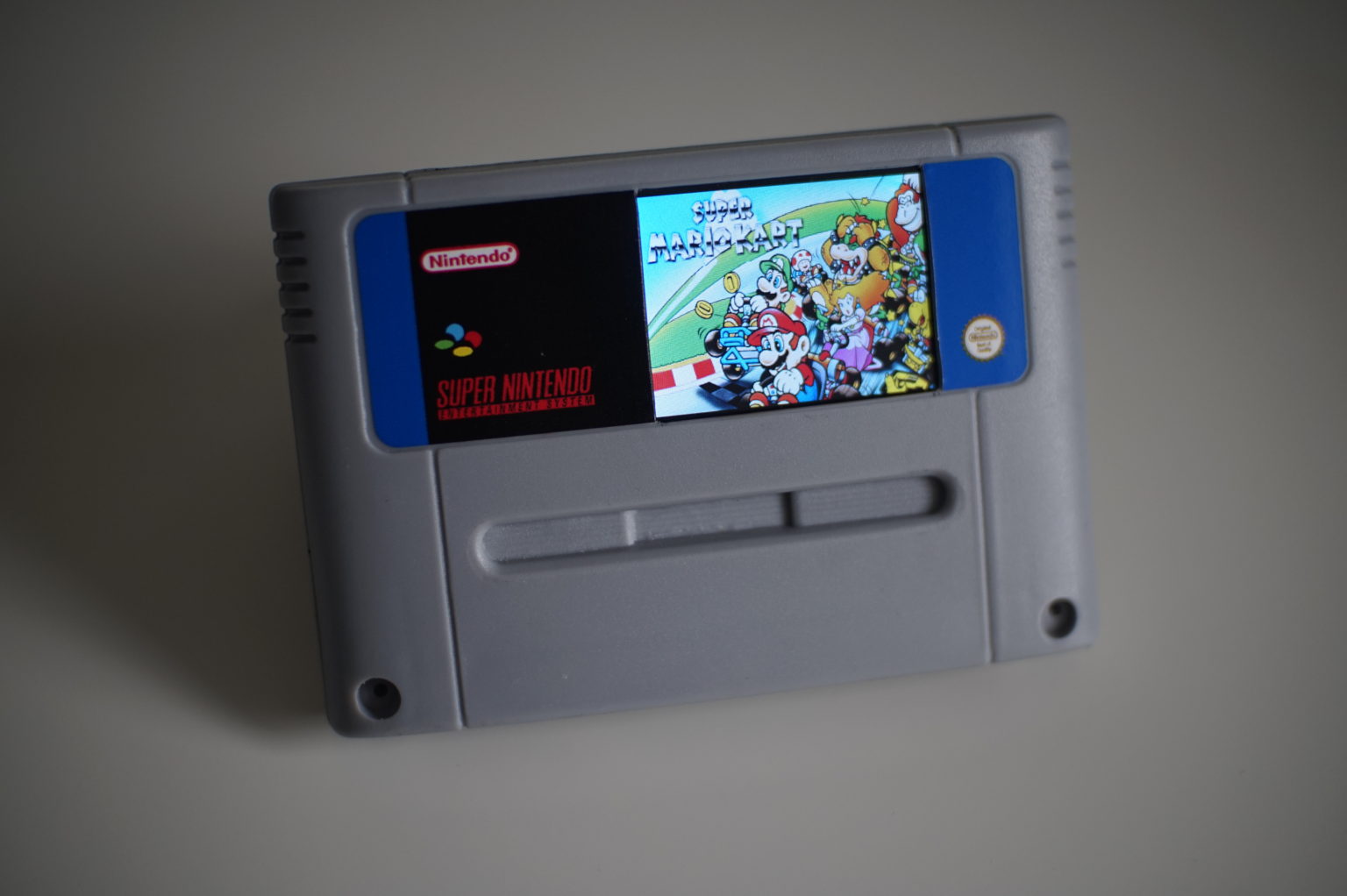
Reproduction Super Nintendo Cartridge – Again, not wanting to destroy a piece of gaming history, I have opted to use a reproduction cartridge. You could always use the case from a faulty game…..or a crap one.
2.2 Inch Colour TFT LCD SPI Display (ILI9341) - 2.2 Inch Colour TFT LCD SPI Display (ILI9341) – This screen fits perfectly inside the case and is pretty much the exact height of the label.
Raspberry Pi Zero W (without header) – This link is for the Pi Zero Starter Kit that does have a few handy components that may come in handy for other projects.
Adafruit PowerBoost 1000 Charger – Rechargable 5V LiPo USB Boost @1A – 1000C – This handy little board lets you plug in a 3.7v LiPo battery to power the entire project.
Adafruit Mono 2.5W Class D Audio Amplifier – PAM8302 – This will run the audio for the project.
8ohm 2W Speaker – Don’t have a link for this one, I managed to re-purpose a tiny flat speaker from a promotional handout I got at an expo years ago.
1200mAh 3.7 v LiPo Battery – I used a PKCell LP503562 1200mAh 3.7v from Pimoroni, but the linked version should work fine.
Sugru Mouldable Glue (optional) – I used this to secure the parts inside the case as it provides a really secure hold for all the boards.
Also, as you can see in the pictures below, I also purchased a few new toys to help me with the build…
Soldering Iron Kit – A must if you want to make sure everything will fit inside the SNES cartridge.
Magnifying Helping Hands – Used to keep things in place and helps with the fine detailed work needed on the Pi Zero.
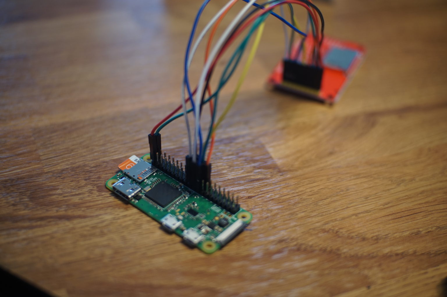
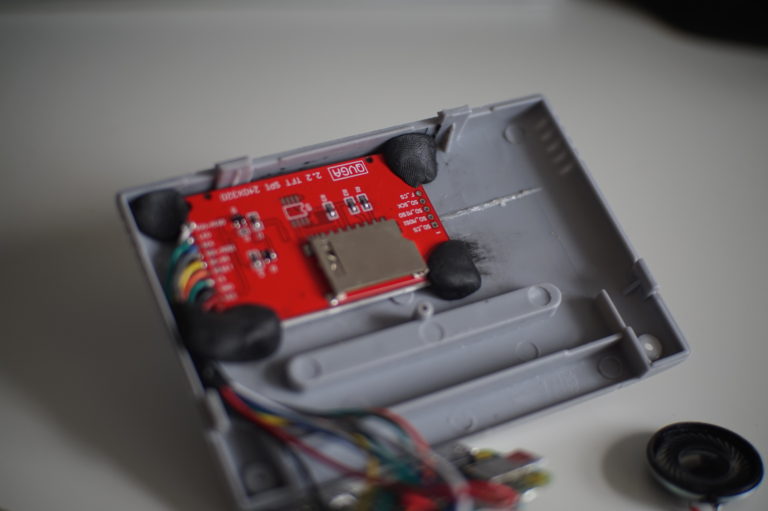
Following the diagram you can see an overview of where all the connections need to go (the above picture was just me testing the correct connections before soldering….recommended!). I have also added the details for each board below…
2.2 inch SPI Display to the Raspberry Pi Zero
VCC – Pin 1 (3.3v PWR)
GND – Pin 20 (GND)
CS – Pin 24 (GPIO 8)
RESET – Pin 26 (GPIO 7)
DC – Pin 22 (GPIO 25)
SDI / MOSI – Pin 19 (GPIO 10 SPIO MOSI)
SCK – Pin 23 (GPIO 23)
LED – Pin 2 (5v PWR)
SDO / MISO – Pin 21 (GPIO 9 SPIO MISO)
There are a few different versions of this SPI screen but the one I used has the above connections ILI9341 (some have additional points for touchscreen functionality, not needed for this project).
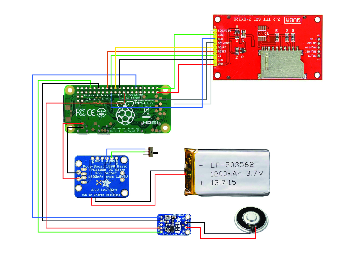
Doing my research on this part I found a few different options for which GPIO to use for the audio, I did originally connect the Amp directly to the 5v and GND on the PowerBoost 1000 but I was getting severe distortion, the way I have detailed it here I did not seem to get any problems, that was to connect the Amp to the Pi Zero using the same GND and 3.3v on the Pi Zero.
Fellow Raspberry Pi enthusiast @raspberrycoulis also made a recommendation to fix any potential sound distortion… “one tip for reducing audio interference – you can add ferrite beads to the wires – you can pick them up really cheap on eBay’ Great guy, go check him out over at raspberrycoulis.co.uk.

Preparing the SD card
Download latest Raspberry Pi OS – HERE
Use Etcher or equivalent to flash image to SD card (64GB for this example)
Place two files in the root directory of the card…
Create a blank text document and add in the details below..
country=gb
update_config=1
ctrl_interface=/var/run/wpa_supplicant
network={
scan_ssid=1
ssid=“INPUTYOURSSID”
psk=“INPUTYOURPASSWORD”
}Rename the file “wpa_supplicant.conf” ensuring you remove the .txt file association. This file will configure the network settings.
Create another blank text document and simply rename it to “ssh” this enables you to SSH into your Raspberry Pi.
Display – (FBCP Framebuffer Copy Method)
With the Raspberry Pi connect to the screen using the GPIO ports, place the SD card in and switch on the power. – (You will not see any activity on the screen as the correct display drivers need to be installed).
Discover the IP address assigned to your Raspberry Pi, you can log into your router or use an app such as ‘Fing’
Once discovered use Terminal (MacOS) or equivalent to SSH into your Pi
$ ssh pi@xx.xx.xx.xx
(default password “raspberry”)
$ sudo apt-get update
$ sudo raspi-config
Make the following amends
7 – Advanced Options
A1 – Expand Filesystem
5 – Interfacing Options
P4 – SPI – Enable
Finish
Once rebooted, SSH into the Pi again and follow the commands below..
$ sudo apt-get install cmake
$ git clone https://github.com/juj/fbcp-ili9341.git
$ cd fbcp-ili9341
$ mkdir build
$ cd build
$ cmake -DSPI_BUS_CLOCK_DIVISOR=20 -DSTATISTICS=0 -DADAFRUIT_ILI9341_PITFT=ON..
$ make -j
$ sudo ./fbcp-ili9341
^c
$ crontab -e
At the end, add the line
@reboot sudo /home/pi/fbcp-ili9341/build/fbcp-ili9341 &
$ sudo nano /boot/config.txt
add the lines (changing the resolution settings if needed)
hdmi_group=2
hdmi_mode=87
hdmi_cvt=240 320 60 1 0 0 0
hdmi_force_hotplug=1
Audio
Whilst editing the config.txt file, now is a good time to sort out the audio output, just add the line..
dtoverlay=pwm-2chan,pin=18,func=2,pin2=13,func2=4
Reboot to make the changes take effect, when back online access the terminal and type
$ sudo raspi-config
Again making the following amends
7 – Advanced Options
A4 – Audio
Force 3.5mm (‘headphone’)
Finish
I have found the best way to adjust the audio is either by lowering the audio in the edited video you plan on displaying or better, is to adjust the on board trim potentiometer on the Adafruit Amp.
Using Adobe Premiere Pro, I put together a video that, similar to the NES cartridge, with the label artwork followed by some captured gameplay…this time paying attention to the audio!
If there is a demand I may upload the video to Facebook or YouTube.
To get the video running on boot, just follow the instructions below..
Use Cyberduck or equivalent to upload the video file you want to play (ensuring that you set the resolution to the resolution of the screen you are using i.e. 240 x 320 and in the correct formatting i.e. landscape or portrait, using Adobe Premiere Pro or similar).
Place the video in your desired directory, for this example /home/pi/Videos
The video will be played using the built in OMXPlayer
For it to run and display the video on start up the following needs to be added to Crontab (using rc.local has mixed results)
$ crontab -e
At the end, add the line
@reboot omxplayer -o local – -loop /home/pi/Videos/YOURVIDEOTITLE.mp4
Exit and save the changes
$ sudo reboot
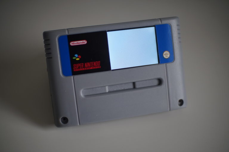
Not much of the internals of the cartridge (structure wise) has to change to fit all the equipment in, just the cutout for the whole and the horizontal support for the curved front.
I put together the artwork for the label using Adobe Illustrator, I had two different versions but ended up using the label with the blue side trims, loads of different carts used different side trims, it is up to you what you want to go for.
If you would like a copy of the artwork, visit and like the Nostalgia Pop Facebook page for the Adobe Illustrator 9 (.ai) file.
I had mine printed by Art-o-Cube on eBay
Marking out the square on masking tape, I used a scalpel and repeatedly went over the lines until going all the way through the case, tidying with a small file. If you had the equipment you could laser cut for better precision.
As detailed at the top of this article, I used Sugru to secure everything in place. If so desired you could drill out a few holes in the back of the cartridge to allow for more sound to escape and for cooling on the Raspberry Pi, however I have chosen not to do that and have had the cart running for several hours without any issue or over heating.
There is PLENTY more you could do, such as the aforementioned RetroPie installation, adding a HDMI output or wherever you like!
As I mentioned, to complete this project I conducted many a Google search and though it was only fair to give them a mention.
Here is a good tutourial I used on how to get the display working, and also a mention for the talented Tinkernut who can be found on his YouTube channel (can in handy when I was trying to get the audio working).
This is not the type of thing you can patent as at the end of the day, a majority of the intellectual property is owned by Nintendo. A project like this is merely a homage to the pixel art goodness of the past…so go out and give it a go!